![]()
![]()
![]()
Teachers Introduction Course to LEGO® Mindstorms NXT & EV3
(version 4.5)
UNIT 9. From sequential programing to state machine: the four step simple line follower with two light or color sensors.
In this pedagogical unit we will see in detail how the four step simple line follower with two light or color sensors works, how to systematize the design of its algorithm, we will analyze the similarity and fundamental difference with the 3 step simple line follower with one light or color sensor, we will see how to make the robot take decisions sequentially at each line intersection, we will learn how to design data flow diagrams to express graphically the working process of a program, and finally, we will see how to program a state machine for this line follower and the advantages it brings over the sequential programing.
Unit 9 exercise 1: 4 step simple line follower with two light or color sensors sequential programing.
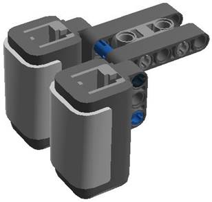
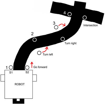
We can start by asking the students how they think we should conceptually proceed, how should we design the algorithm? Note that the two light or color sensors are located in both sides of the black line to follow, as shown in the images below, where we can observe that adding them to the robot is trivial.
|
|
|
|
|
|
We can help the students by making a small drawing in the blackboard and asking them:
- What should the robot do when the two sensors detect (or “see”) the white color? By making the drawing it becomes obvious that robot has to go forward.
- And when the left sensor detects black and the right one white? It has to turn left.
- When the right sensor detects black and the left one white? It has to turn right.
- Finally and before drawing the intersection we can ask in what situation the two light or color sensors of the robot will detect black. The answer is: in an intersection.
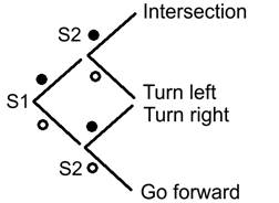
Another more systematic but less graphic way to find all the combinations of the two light or color sensors’ readings is to build a table of values.
|
Light or color sensor values |
|
Sensor 1 (left) |
Sensor 2 (right) |
Robot action |
|
B = Black |
|
B |
B |
Intersection, stop the robot? |
|
W = White |
|
B |
W |
Left turn |
|
|
|
W |
B |
Right turn |
|
|
|
W |
W |
Go forward |
|
|
|
(port 2) |
(port 3) |
|
We can ask the students how many combinations we would have with 3 light or color sensors. The answer is 8 wich is equivalent to 23. In general we would have XY, where X is the number of possible readings –in our case 2, that is, true if the reading is below the threshold between white and black and false if it is above– and where Y is equivalent to the number of sensors, in this example 3 sensors.
Next we can ask how to program this line follower? We can help the students by asking them how many different options we have. The answer is 4, thus we will need a switch with 4 branches. How can we obtain these 4 branches? Well, we need to nest 3 switches. At the same time that we ask them these questions, it is important to draw in the blackboard the pseudo-code to help students visualizing the algorithm and asking them what needs to be drawn meanwhile drawing it. An important point they need to understand is that the first switch needs to be associated to the first light or color sensor and the other two to the second one, to obtain the 4 possible cases, like shown in the image below.
At this point the programing is trivial, we only need to implement the previous pseudo-code. Remember that the right wheel is connected to port B motor and the left one to port C, and that the left light or color sensor is connected to port 2 (previously you need to disconnect the sound sensor) and that the right one is connected to port 3. You will also need to check the right value of the light threshold between the white color of the field backgroung and the black color of the line to follow. In NXT programing software the light sensor 50% default value works in almost all cases, and in EV3 programing software, with the color sensor configured to read the reflected light, you will need to lower the threshold value to 25%, for example. Finally, you will also need to adjust the motors’ power to be less than 50% to obtain a smooth robot behavior when following the line, in EV3 programing software and with EV3 motors, this value needs to be a little bit lower than in NXT.
Create a new program, for example “u9ex1.rbt”, as shown in the following image.
4 step simple line follower with 2 light sensors (NXT)
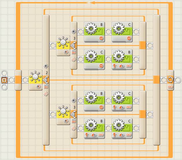
4 step simple line follower with 2 color sensors (EV3)
As mentioned before, we can see that, in both programs, even if the block motors are located one after the other –to start or to stop them at the same time, or to stop one and start the other one–, the program execution is so fast that it is like the two are run at the same time. In the case of the EV3 program, there is a block called “Move Tank” that is very useful to control the 2 motors at the same time with only one block. The image below shows how to simplify the previous program using this block.
4 step simple line follower with 2 color sensors
using the block “Move Tank” (EV3)
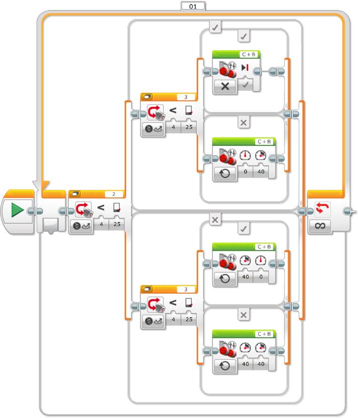
Tip: When using the “Move Tank” block you need to carefully configure the block’s motor ports, from left to right, in the same way the motors are setup in the robot looking towards the front (“Left Motor Port + Right Motor Port”). In our example, we need to configure the motors as “C + B” (and not “B + C”) because port C corresponds to the motor on the left and port B to the one on the right. We can also see that to brake a motor you just need to configure its power to 0.
Finally, if the robot executes the program, what will be the robot’s behavior? The answer is that the robot will follow the line until the first intersection and once there it will stop and it will never get out of the loop, that is, the program will execute indefinitely (until the batteries will run out or until we will stop it). To demonstrate this, we can raise the robot and place it a little bit further away from the intersection, just after it, and we will see how the robot will start again following the line until the next intersection, etc.
Next, we can recall the algorithm of the 3 step simple line follower with only one light or color sensor and ask the students what is the fundamental difference with the previous 4 step simple line follower with 2 light or color sensors?
3 step simple line follower with one light sensor (NXT)
3 step simple line follower with one color sensor (EV3)
As we have previously seen, you need to make several tests to adjust two thresholds with enough distant values (for the same light sensor in NXT or color sensor in EV3) to make the robot go forward in the straight segments and not to lose the line in the curves.
Observe that the behavior of the previous algorithms to follow the line with one or two light or color sensors is almost identical (maybe it is a little bit more precise with two light or color sensors) because both algorithms execute 3 steps. In the case of the line follower with one light or color sensor, the robot turns to one side or to the other and goes forward whenever the reflected light detected by the light or color sensor is close to the threshold between white and black, in other words, when the sensor “sees gray”. In the case of the robot with 2 light or color sensors, the robot goes forward when the two light or color sensors detect white, that is when the black line is just in the middle of the two light or color sensors.
Thus, the fundamental difference is that the robot with two light or color sensors is capable to detect line intersections!
Coming back to the algorithm of the line follower with two light or color sensors, we can now ask what we need to do when the robot detects an intersection. With the current students’ knowledge the correct answer is to get out of the loop!, so as to decide what to do at each intersection, that is, to go forward, to stop or to turn to one side or to the other of the intersection. Some students might see that another solution will be to count intersections, but we will address this later…
Then the question is: how can we get out of the loop? In general, when we use a loop the problem is always how to get out of it… The answer is by using a variable. For this, we need to convert the loop into a logical loop and use a logical variable to control the exit from the loop when finding a line intersection.
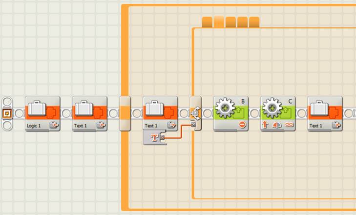
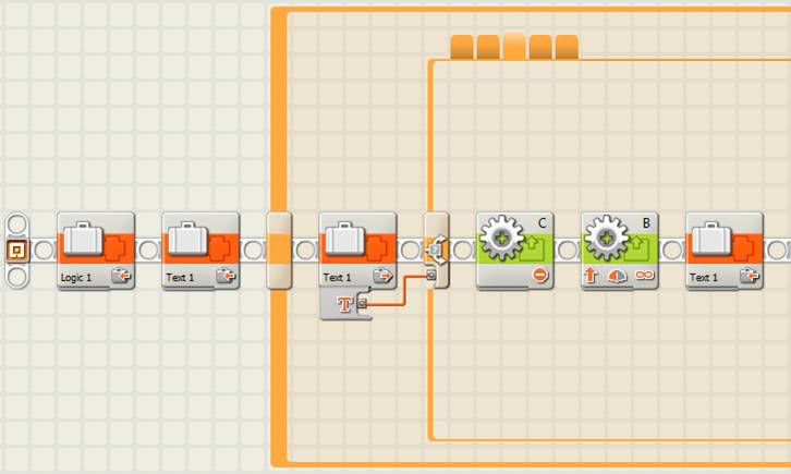
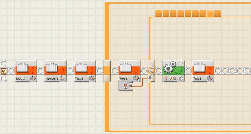
4 step simple line follower with 2 light senors
with loop exit control when detecting a line intersection (NXT)
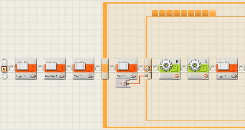
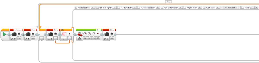
4 step simple line follower with 2 color senors
with loop exit control when detecting a line intersection (EV3)
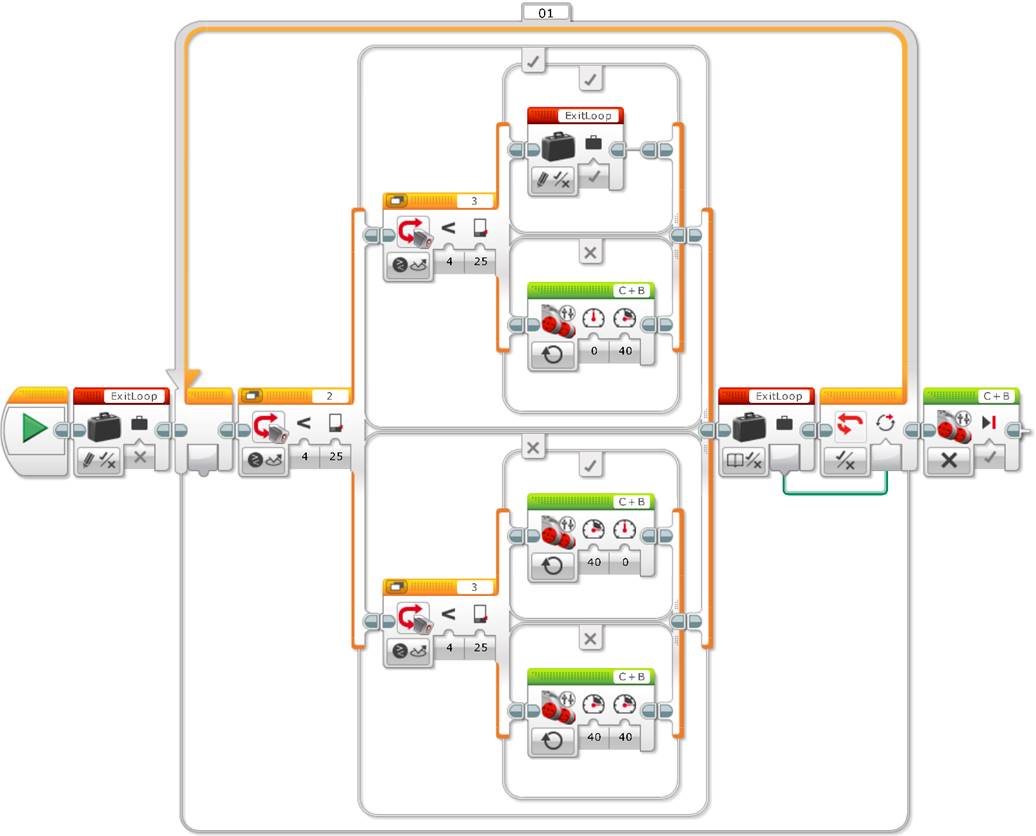
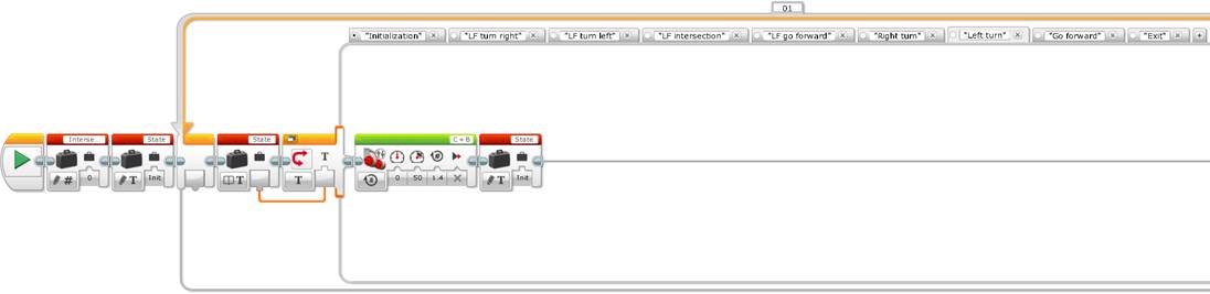
If we pay attention to the previous codes, the logical variable initializes to false, that is, it is written to a false value before entering the llop, and it is only written to “True” when the light or color sensors detect the black color to make the robot exit the loop. We can also see that the motors are stoped just after exiting the loop. We could have done this inside the switch, but as we will see later on, doing this outside the loop gives more flexibility.
Observe that initializating the variable before entering the loop saves having to insert the variable 3 more times in each one of the other 3 switches’ branches, but with a false value. In addition, it makes it easier to read and understand the program.
A little bit of theory
Some programing languages explicitly require initializing variables, but this is not the case of Mindstorms NXT-G or EV3. By default, a logical variable is initialized to the false value, a numeric variable to the 0 value and a text variable to the empty string, meaning “”.
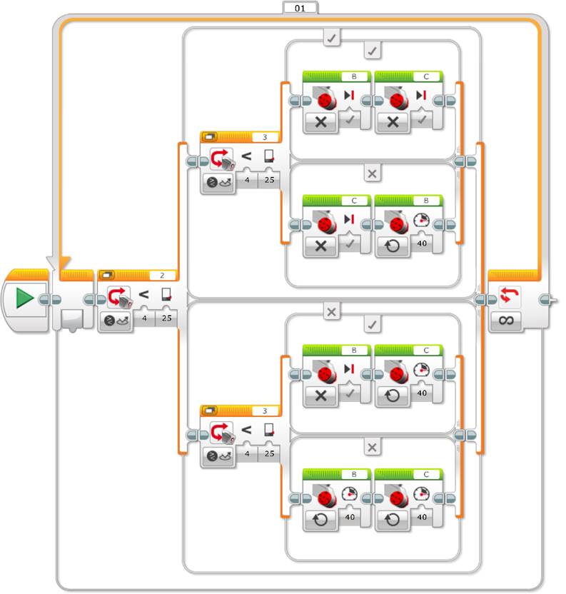
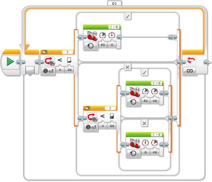
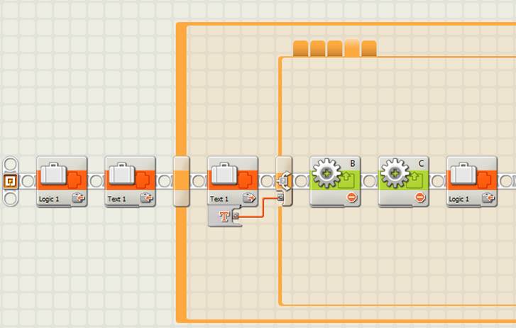
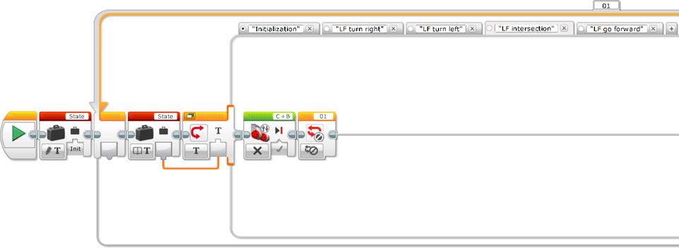
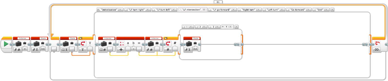
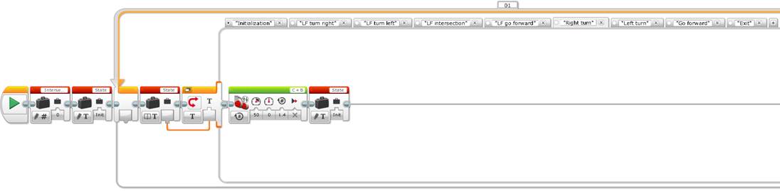
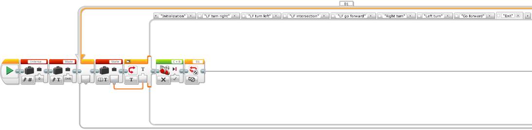
Finally, the EV3 programing language has a “Loop Interrupt” block that allows getting out of a loop, which saves the use of a variable, as the following image shows. Observe that the “Loop Interrupt” block needs to have the same name as the loop you want to interrupt. By default, loops are numbered meanwhile you are adding them to the program and their number can be changed by any name. In our example the loop is named “01” like its “Loop Interrupt” block.
4 step simple line follower with 2 color sensors
with loop exit control using a “Loop Interrupt” block (EV3)
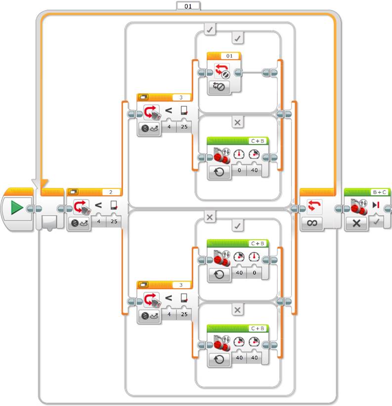
Tip: It is a very good practice to always initialize the variables used, so as to make explicit their values and to make the code much more understandable. In EV3, if you use a “Loop Interrupt” block make sure that its name is the same as the loop you want to interrupt. In the case of long and complex programs it is very advisable to use descriptive names for loops, to better understand the code when we use the “Loop Interrupt” block.
You can now build a small circuit with intersections and you can ask the students to program the robot to go forward at the first intersection, to turn left at the second, to turn right at the third and to stop at the fourth one. The solution is very easy, you only need to copy the previous code and program what the robot needs to do at each intersection, just after each loop exit.
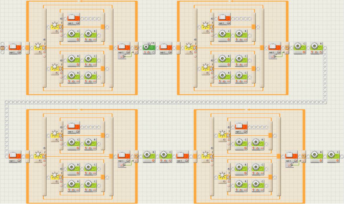
After the first intersection the previous programs use a Move block in NXT and a Move Tank block in EV3 to make the robot go forward 70 degrees, just enough to surpass the line. At the second intersection the robot makes a point turn, in this case over wheel C, to turn left. We can see that, with a stoped wheel, if the other motor turns an equivalent to one rotation, given the robot’s geometry, this makes exactly one quarter turn, just what we need to continue following the line. At the third, the robot turns over the other wheel to turn right, and at the fourth intersection the robot stops. At this point we see the usefulness of not putting the motor blocks to brake them and stop the robot inside the switch branch corresponding to the line intersection detection, this saves some code and allows concatenating the robot movements in a softer way without motor brakes.
But even if this solution works perfectly well, what is its disadvantage? The problem is that the program is too long, meaning that the corresponding line follower code is duplicated four times, or as many times as intersections to negociate. This implies that if we need to change the line follower program, we will need to repeat it four times in this case, and in addition, the program needs to compile, or translate to the robot’s CPU language, four times the same code, what makes the program less efficient and uses a lot of unnecessary space in the robot’s memory.
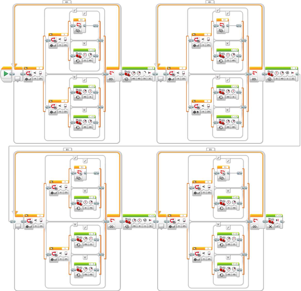
The following step is to create a subprogram or user block “LineFollower2s” for the code corresponding to the line follower that is duplicated four times in the two previous examples.


Now the program is much more efficient and easy to understand, and the code corresponding to the line follower is only compiled or translated to the robot’s language once. In addition, if we need to make a change in the subprogram or user block, we only need to do it in the original program and when saving the change, this will propagate to all the instances or its insertions inside the main program.
Finally, we can design a longer circuit to test the robot in taking decisions at each line intersection in a sequential way, following the flow or sequence of the robot path.
Acquired knowledge: The students have learnt designing algorithms in a graphic way, with pseudo-codes and in a systematic manner by using tables of values for each sensor. They have also compared the algorithms of the line followers with one and two light or color sensors, and they have seen a sequential strategy to program the line follower robot with two light or color sensors to make decisions at each line intersection. In addition, the students have seen the usefulness and efficiency of subprograms or user blocks to make the code more compact and more understandable and efficient, and they have learnt to use variables to pass information between different blocks or program parts, especially to get out of a loop using a logic control in NXT (or with a “Loop Interrupt” block in EV3).
Incremental exercise 9: Get to the end of the jail using a simple line follower with two light or color sensors and making the code more compact with a user block.
Before starting, we can copy the previous incremental exercise 8 and give it a different name, so as to keep a copy. Next we just need to substitute the user block “LineFollowerP” with the previous subprogram code of the line follower with two light or color sensors “LineFollower2s”. In any case, we need 6 instances of the line follower user block and between each instance we need to turn left, go over the middle line of the field, turn right, turn right again, go over the middle line again and stop.
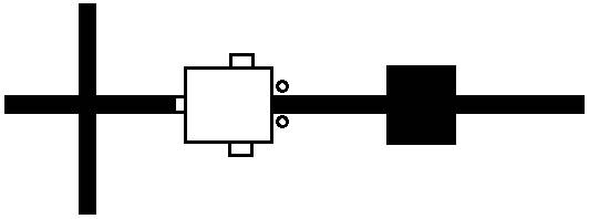
The image below shows the circuit of the incremental exercise to reach the end of the jail, where the arrows show the robot’s actions. The straight forward movements where the robot will have to follow the line are shown in black and the actions the robot will have to make in reaching the intersections are shown in red.
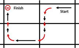
Tip: To make the robot easily detect intersections, these need to have a cross shape (“+”). If the diversions in the middle of the field have a “T” shape, then you need to add some tape to generate a cross so as to make the light or color sensors easily detect them. This might not be necessary, what will depend on the robot’s geometry (distance of the sensors to the wheels turn axis and distance between wheels) and the speed of the motors when following the line.
A little bit of theory
The previous programing style is perfectly correct, the blocks and decisions are programed in a sequential way following a specific order, for example, following the order in which the robot encounters the intersections, following a specific reading order of the different robot’s sensors, and finally taking actions in function of a specific sequence of decisions. In Mindstorms NXT-G or in EV3 the sequence beam establishes the program blocks execution order. The sequential programing is one of the most common and often more obvious programing styles, because if the program is not very complex, you can write it without any planning, but it is not always the most efficient, most flexible or most understandable style in the long run.
For example:
- What happens if we have to change the order of intersections, the order of the sequence?
- What happens if we have to repeat several times one or several sequence components, for example, to repeat several turns to one side, or to go forward on several different lines of the path?
- What happens if we have to execute a sequence part only when a specific condition is met, for example, if we have to add a third ultrasonic sensor to make the robot avoid an obstacle in the middle of the path?
- What happens if we want to stop immediately the execution of the program when a specific condition is met and we do not want to wait until the rest of the sequence is finished?
Can we improve the sequential programing of the 4 step simple line follower with 2 light or color sensors and make it more functional, more compact and even better understandable? The answer is yes, by using a state machine.
The state machine programing model is a very common and useful model that allows implementing any relatively complex algorithm that can be represented by a data flow diagram with its decisions making processes and its resulting actions.
A state machine (or finite state machine) is based on a series of states with a transition function which sets the next state to take. Each state contains an action to take and a transition code that allows calling the next state. Often the programs or applications require an initialization state, followed by a default state –where for example, the sensors are read to make decisions and to call other states or to take different actions– and finally, it can have a closing state to take cleaning actions before finalizing the program.
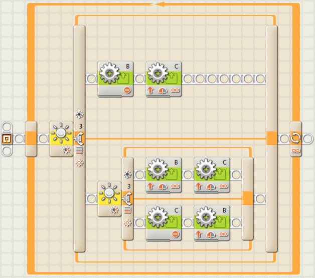
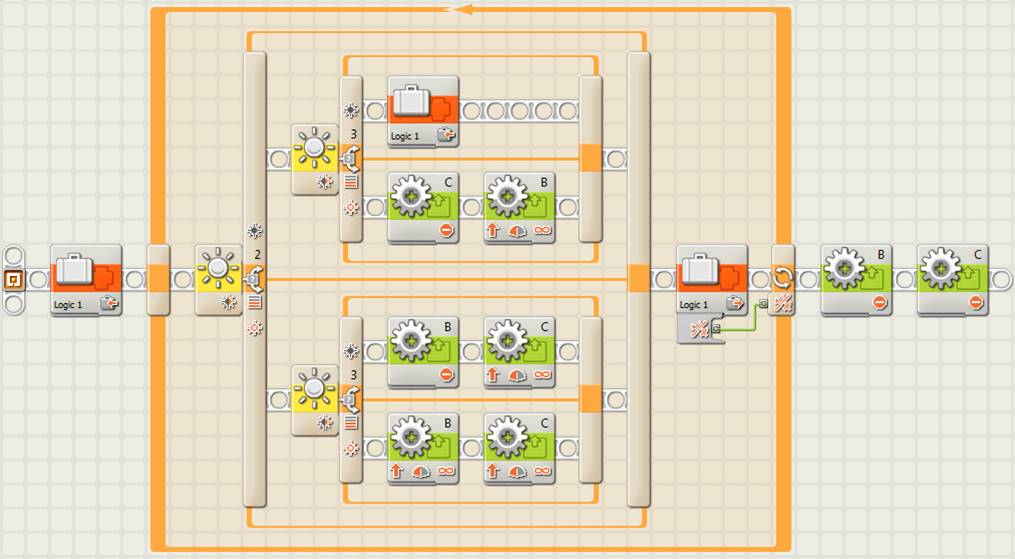
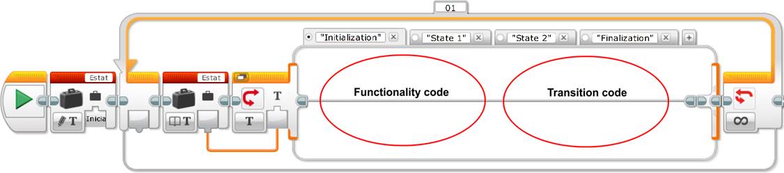
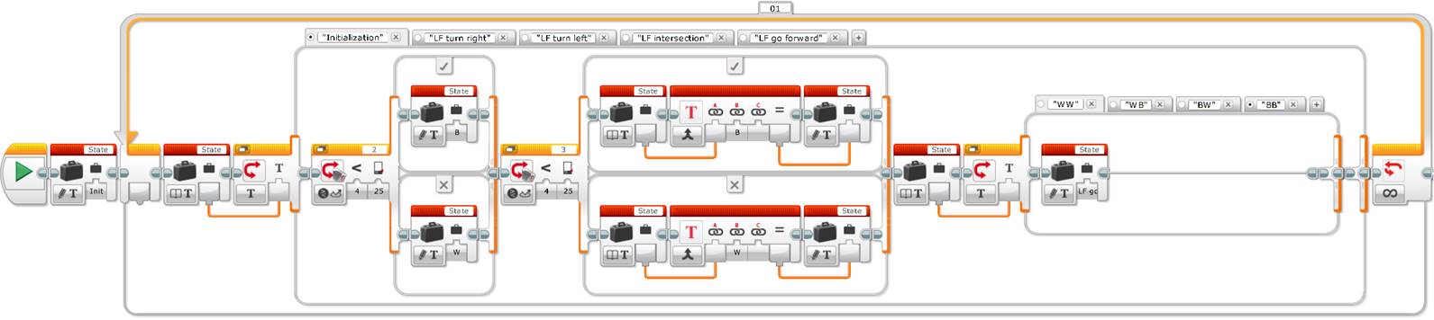
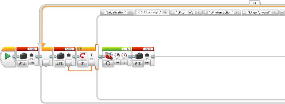
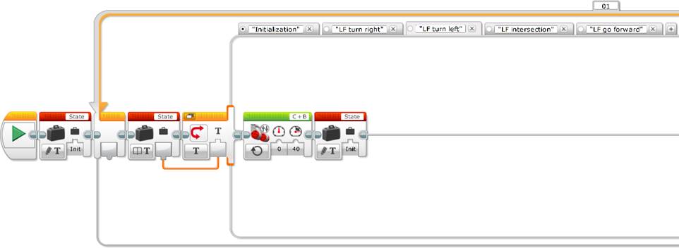
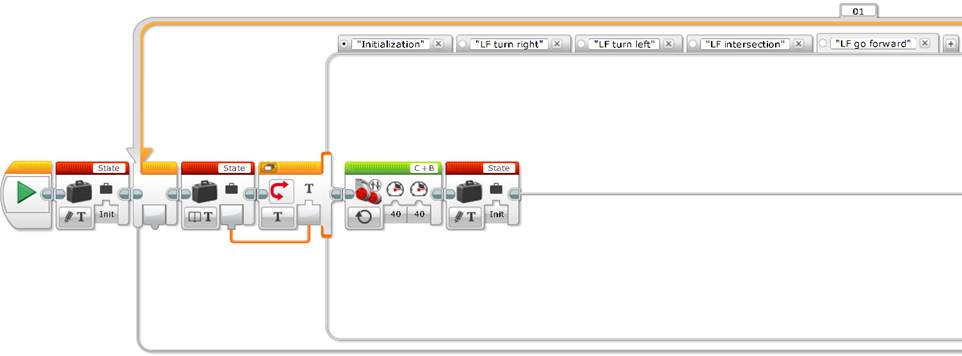
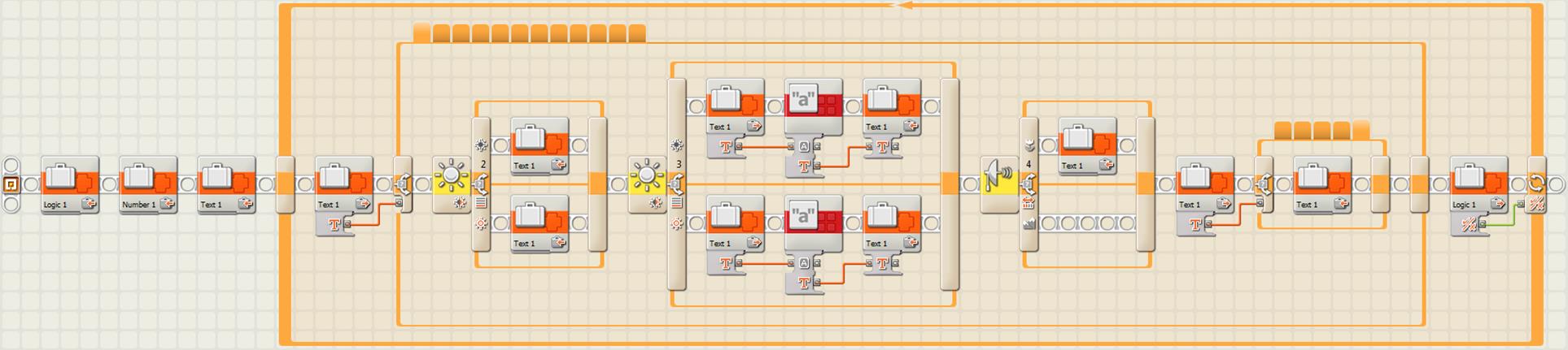
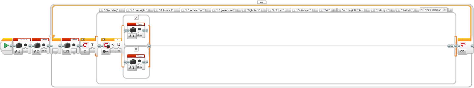
In Mindstorms NXT-G and EV3 we can create a state machine with a loop, a case structure or multiple switch –where each case represents a state–, a variable to store the transition information between states at every iteration of the loop, a functionality code for each state and a transition code that allows to determine the next program state. To get out of the loop, in NXT we need to use a logical loop and a second logical variable, initialized to false, that will only be set to true in the finalization state so as to get out of the program. In EV3 the loop can be unlimited and we only need to add the “Loop Interrupt” block in the finalization state. Finally, we can define the state machine default case to the initialization case. In the following example, the state machine structure has 4 cases represented by the 4 case structure tabs: “Initialization”, “State 1”, “State 2” and “Finalization”.
State machine basic elements (NXT)
State machine basic elements (EV3)
Unit 9 exercise 2: Construction of a state machine for the 4 steps simple line follower with two light or color sensors.
We can start by asking the students how many states they think the state machine of the 4 steps simple line follower with two light or color sensors will have. It is very probable that they will say 4 states, one for each case or step of the line follower, that correspond to each one of the actions, which are, to go forward, to turn to one side or to the other side, or to get out of the program when reaching a line intersection.
The first point to consider when creating a state machine is to separate the decisions from the actions that the program needs to take. In this way we need to separate the sensors’ reading from the actions that the line follower will have to take at every loop iteration. Thus, a first state, that could be the initialization state, will correspond to the reading of the two light or color sensors that will determine what will be the next state to execute. This next state will contain the action that the robot will have to do, meaning the functionality code, and it will call again the initialization state to read again the sensors, meaning the transition code. The state corresponding to the case when the robot finds a line intersection allows it to get out of the loop, which means to get out of the program, as it is shown below.
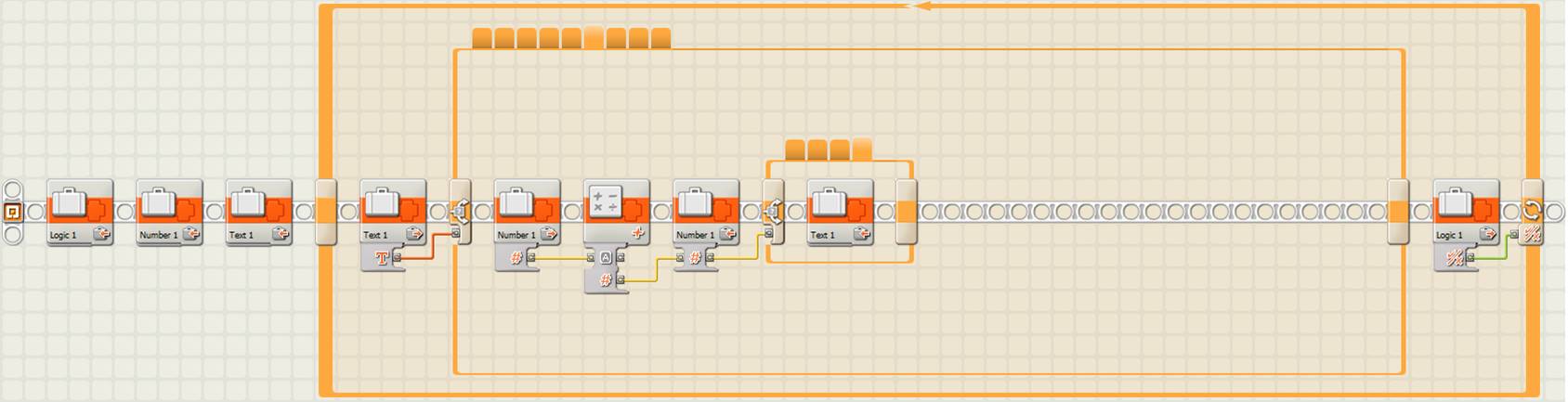
Create a new program, for example “u9ex2.rbt”, as shown in the following image.
State machine for the 4 steps simple line follower
with 2 light sensors, initialization state (NXT)
|
|
Case “LF turn right”
|
|
|
Case “LF turn left”
|
|
|
Case “LF intersection”
|
|
|
Case “LF go forward” |

State machine for the 4 steps simple line follower
with 2 color sensors, initialization state (EV3)
|
|
Case “LF turn right”
|
|
|
Case “LF turn left”
|
|
|
Case “LF intersection”
|
|
|
Case “LF go forward” |
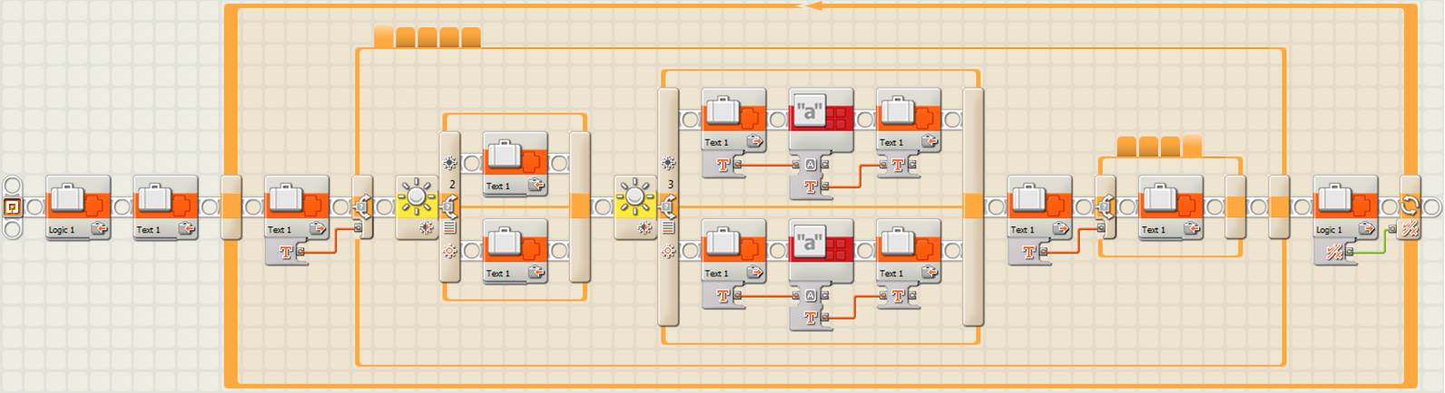
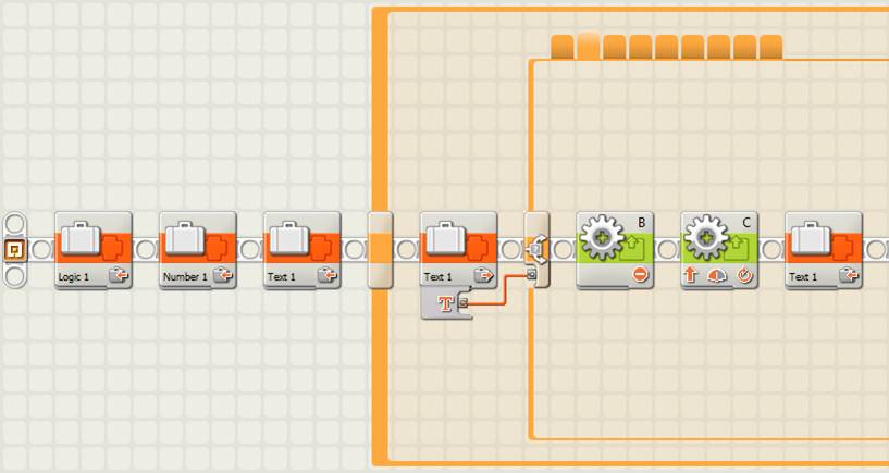
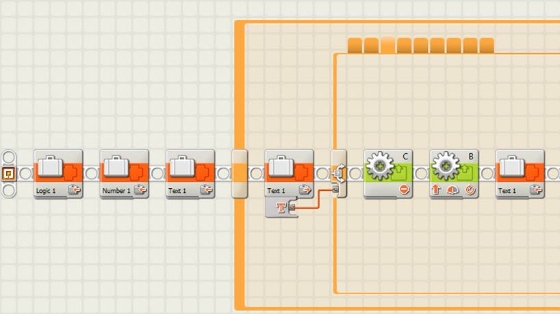
The first point we can observe in the previous programs is that the initialization state –where the line follower reads the two light or color sensors and makes the state machine decisons– uses a text variable to store the two possible values, first the value of the first light or color sensor on the left (port 2), which can be “B” for black or “W” for white, and second it concatenates the readind of the second light or color sensor on the right (port 3), which can also be “B” or “W”. Thus, the result is a two character string that can have the following values: “WW”, “WB”, “BW” or “BB” corresponding to the 4 possible combinations of the two light or color sensors outcomes. These values can also be used for the states of the state machine, but why they are not used? The students will need to think a little bit…
The answer is: because they correspond to the reading of the sensors (the functionality code) and not to the state that we are really interested in calling in the program’s state machine (the trasition code between states). In other words, after obtaining each different combination of the light or color sensors, in our case, “WW”, “WB”, “BW” or “BB”, we need next to call the adequate state, in our case, “LF go forward”, “LF turn right”, “LF turn left” or “LF intersection” respectively. This is done by using a second case structure or multiple switch that, in our example, reuses the same previous text variable to store the resulting state for each case. This example is very simple, but further on we will see the usefulness of this methodology, that makes the program much more understandable and self explanatory.
Acquired knowledge: The students have learnt to design the first state machine and to understand how to take apart the decision making process of the program from its actions, to understand the difference between the functionality code and the transition code between states, and to understand the differences between the sequential programing and the state machine programing style.
The next step is to modify the previous state machine to make the robot capable to make the adequate decisions to negociate each line intersection of the path. We can ask the students how to do it? The answer is that the state machine should be able to count intersections (some students might have probably answer this at the beginning of the previous exercise) and in function of the intersection number take the correct action, that is, go forward to surpass the line, turn to one side or to the other, or brake the motors and exit the program.
Now we can ask the students again where to place the intersections counter and how to program it? It is obvious that the robot will have to count the intersections that it encounters through the path when both light or color sensors detect black and that we will have to add a numeric variable to store this number. In terms of programing, we will need to add a special state to count intersections and to decide what state to call for each one of these, and 4 more states for the 4 possible actions, previously mentioned, that the robot will have to do at each intersection (to go forward to surpass the line, to turn to one side or to the other, or to brake the motors and exit the program).
A little bit of theory
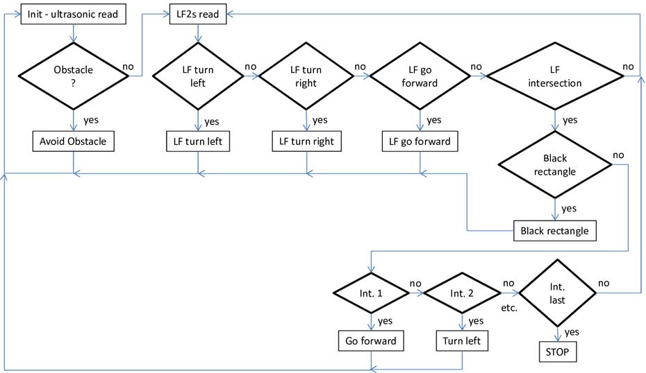
When we write a program we do not usually start writing the code directly, we need a minimum planning, especially if the program is a little bit complex. Even before writing a pseudo-code, as we have seen before, we need to design the so called data flow diagram. A data flow diagram (DFD) is a graphic representation of the data flow through an information system that can be also used to visualize the data processing. In our case we can use it to visualize and graphically differenciate the program parts that read data, the parts that make decisions from reading the data, the parts that do the actions according to each decision and the program’s data flow that connects all the previous parts. If a data flow diagram is well done writing the code can be very simple.
Data flow diagrams can be represented in several ways and with more or less detail. In our case, we will represent the actions with a rectangle, the decisions with a diamond and the data flow with an arrow. Every time a decision is made we will inform the arrow that goes out from the diamond about whether the decision corresponds to a “yes” or a “no”.
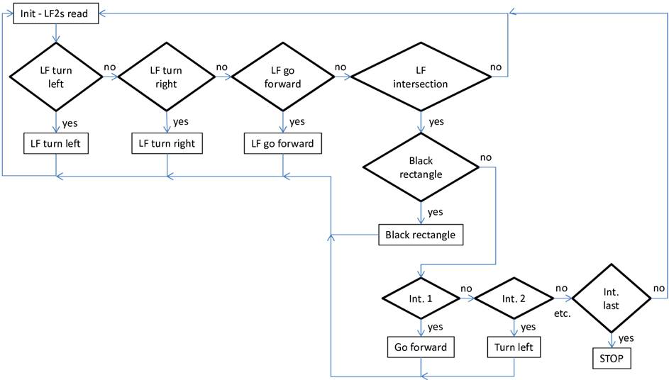
Data flow diagram of the 4 step simple line follower
with 2 light or color sensors with intersection management
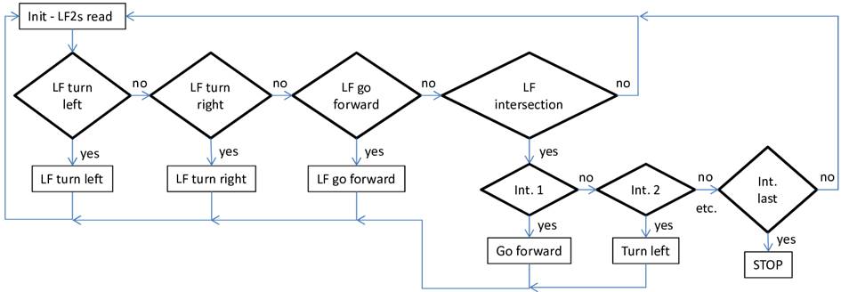
As we can see in the above data flow diagram, the upper rectangle “Init - LF2s read” reads the light or color sensors data. Next, in function of the sensors’ reading, decisions are made (represented by diamonds) about what actions to call. Finally the adequate actions are called, that are shown in the lower rectangles. After each action the initialization state is called again until the system detects the last intersection and exits the program.
State machine of the 4 step simple line follower with 2 light sensors
with intersections management, “LF intersection” state (NXT)
|
|
Right turn
|
|
|
Left turn
|
|
|
Go forward
|
|
|
Exit |
State machine of the 4 step simple line follower with 2 color sensors
with intersections management, “LF intersection” state (EV3)
|
|
Right turn
|
|
|
Left turn
|
|
|
Go forward
|
|
|
Exit |
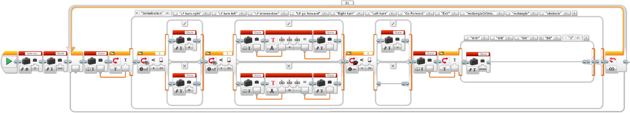
In the previous programs it is very important to note that the case “LF intersection” counts the intersections and for each one of them it establishes the next case to execute in the state machine by means of the text variable. In other words, it does not execute anything, it only makes the decision. This is very important because when doing the incremental exercise with the state machine we will see that we can have several intersections with the same required action and this methodology avoids duplicating the code, systematically setting apart the decisions from the actions.
Incremental exercise 10: Get to the end of the cage using a four step simple line follower with two light or color sensors programed with a state machine.
Before starting we can copy the previous exercise “u9ex2.rbt” and give it a different incremental exercise name. Next we can ask the students what needs to be changed in this program to do this incremental exercise. The answer is that we only need to change the structure of the cases defining the state we need to call for each intersection number, which is inside the “LF intersection” state (1: left turn, 2: go forward, 3: right turn, 4: right turn, 5: go forward and 6: exit). As we can see, the modification is trivial.
Acquired knowledge: The students start realizing the big advantage of separating systematically the program decision making process from the actions in the design of a state machine, what avoids duplicating the code and makes it much more understandable and self explanatory, more compact, more efficient and much more flexible to introduce changes in the future. Once all the states containing all the possible program actions are written, we only need to program the decision making states and the transitions, which is where the program intelligence lies. The students have also learnt to generate data flow diagrams to graphically represent the program flow. Finally, even if we can use a numeric variable to name every state, the advantage of using a text variable is that the program is much more understandable, self explanatory and does not need comments.
Finally, we can add a little bit more of complexity and interest to the previous state machine with the two following examples.
Unit 9 exercise 3: Add the detection of a black rectangle to the 4 step simple line follower with two light or color sensors state machine.
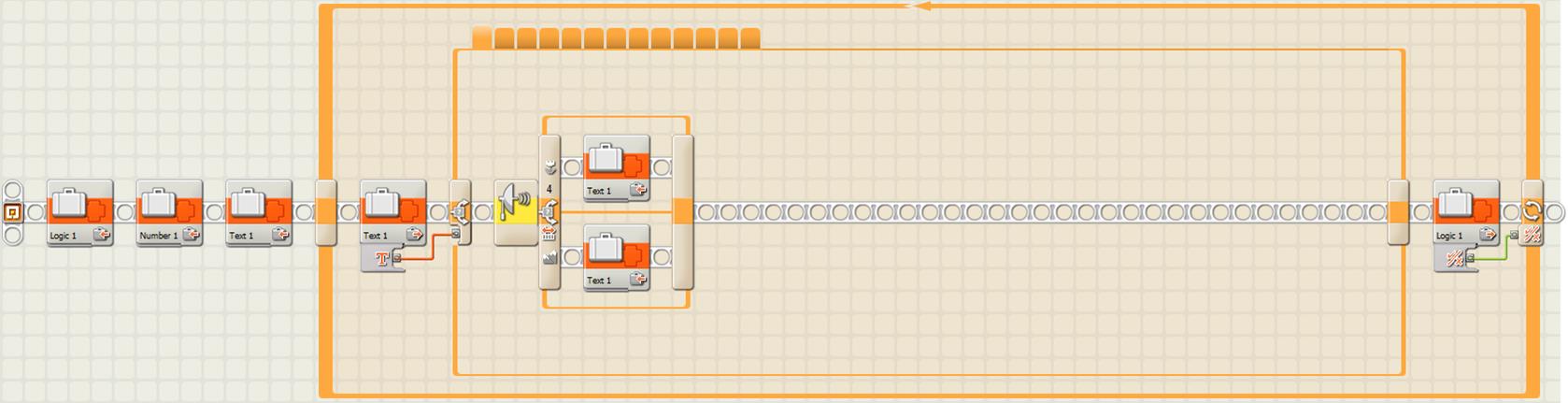
The challenge of this exercise is to create a black rectangle on a straight line in the middle of the path and make the robot capable of differenciating this rectangle from an intersection. In addition, we can make the robot say the word “black”, when it finds the black rectangle, and make a different sound at every intersection to show the hability of the robot at recognizing the intersections and at differenciating them from the black rectangle.
Black rectangle layout in the middle of the robot path
What do we need to modify and add to the previous program state machine to make the robot detect the black rectangle? The answer is that when the robot detects the intersection, we need to add a code that will allow differenciating an intersection from the black rectangle. The following data flow diagram shows the change we need to make to the previous program to differenciate the black rectangle from a line intersection.
Data flow diagram of the 4 step simple line follower with 2 light or color sensors
with intersections management and detection of a black rectangle
Now we need to program the code that will allow the robot to differenciate a line intersection from the black rectangle. How can we do it? We can start by asking the students what differenciates the black line from the rectangle? The difference is obviously the width! So what can we do to make the robot detect this width? If we remember the previous exercises, especially the ones in the pedagogical unit 3, we will see that a good option is to make the robot go straight forward when detecting an intersection until one of its light or color sensors detects the white color. If in addition, the robot counts the rotation degrees of one of its motors (both turn equally) then we will be able to see that the rotation degrees are much lower on the intersections than on the black rectangle.
Remember to create a new program, for example “u9ex3.rbt”, by copying the previous program before starting modifying the code.
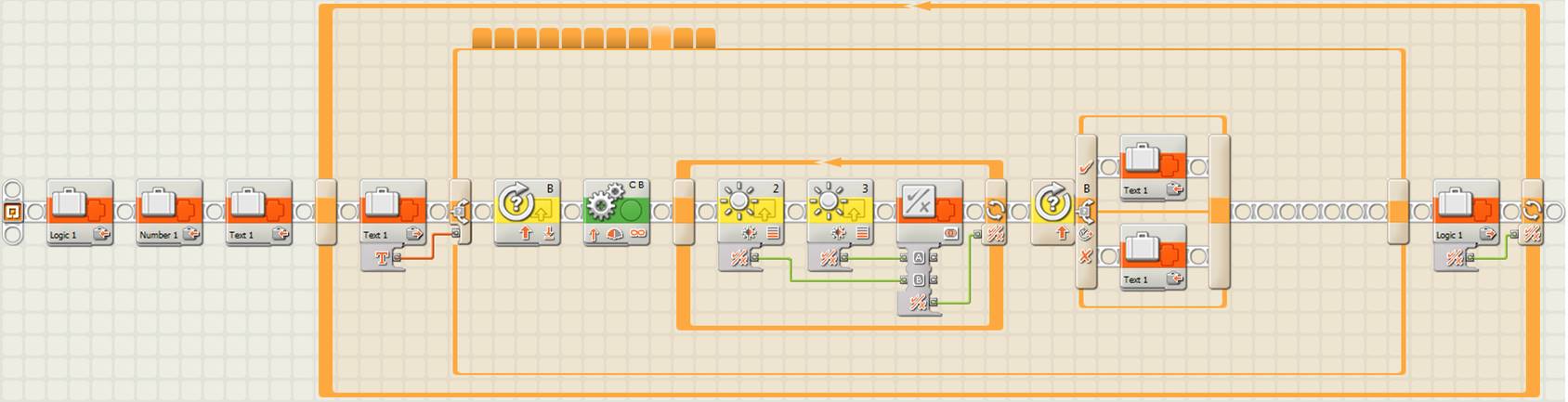
4 step simple line follower with 2 light sensors state machine with intersections
management and detection of a black rectangle, “rectangleOrIntersection” state (NXT)
4 step simple line follower with 2 color sensors state machine with intersections
management and detection of a black rectangle, “rectangleOrIntersection” state (EV3)
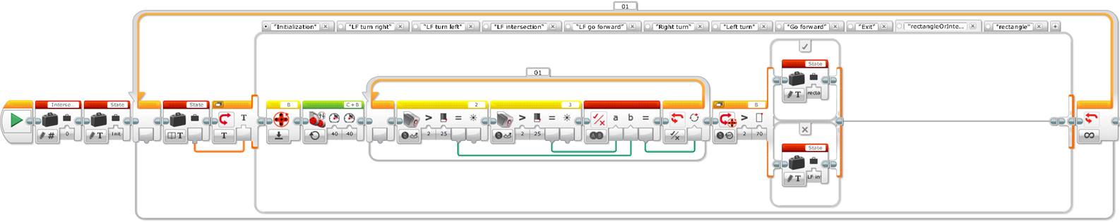
The previous images show the “rectangleOrIntersection” state which is executed just after the state machine detects an intersection. We can see that the code starts by initializing motor B rotations counter, then starts both motors and, using a loop, it waits until one of the two light or color sensors detects the white color, to finally set the state variable to “rectangle” if the rotation degrees of motor B are bigger than 70 or to “LF intersection” if they are lower. Finally, we only need to change the initialization state variable to the value of “rectangleOrIntersection” for the case “BB”, we also need to create a second state in the state machine called “rectangle” to make the robot say “black” and to call the initialization state, and we need to add another sound block to the “LF intersection” state to make the robot do a different sound from the rectangle one at every line intersection.
Unit 9 exercise 4: Add the detection of an obstacle to the 4 step simple line follower with two light or color sensors state machine.
Finally, a last exercise can be to add an obstacle in the middle of the path and program the robot to detect it, negociate it and continue its path without crashing against it.
To solve this challenge, the students need to realize that the robot will have to use a third sensor, the ultrasonic sensor. Thus, what are the minimum changes we need to do in the previous program to solve this challenge and where do we need to add them? Basically, we will need to change the initialization state by adding a code for the ultrasonic sensor. Then, when the ultrasonic sensor will detect an obstacle, it will call a new state “obstacle” of the state machine to make the robot go around the obstacle, and if does not detect any obstacle it will call one of the previous states of the state machine.
Alternatively, we can create a specific state for the ultrasonic sensor reading and convert it into the initialization state, which means that we will call it before calling the decision making state corresponding to the light or color sensors. If this new state detects an obstacle, it will call the “obstacle” state to negociate the obstacle, and if does not detect it, it will call the light or color sensors reading and decision making corresponding state.
Before starting to write any code, we first need to design a new data flow diagram and we can do it for the two previous programing strategies.
Data flow diagram for the 4 step simple line follower with 2 light or color sensors with
intersection management, black rectangle detection and obstacle detection (version 1)
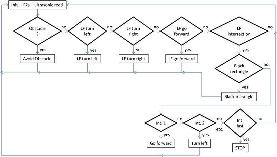
Data flow diagram for the 4 step simple line follower with 2 light or color sensors with
intersection management, black rectangle detection and obstacle detection (version 2)
The difference between both solutions is subtle. The first alternative has the advantage that the decision making code is compacted into one unique state. But at the same time, this is its disadvantage because it makes the code less flexible to change it in the future, since it mixes different types of sensors readings (the two light or color sensors and the ultrasonic sensor)…
Before starting to write the program, remember to create a new program by copying the previous one to allow modifying its code. Given that we will make two versions of the same program, we can name them “u9ex41.rbt” and “u9ex42.rbt”.
State machine of the 4 step simple line follower with 2 light sensors with intersection
management, black rectangle detection and obstacle detection, “Initialization” state
(version 1, NXT)
State machine of the 4 step simple line follower with 2 color sensors with intersection
management, black rectangle detection and obstacle detection, “Initialization” state
(version 1, EV3)
As we can see in the previous images, in terms of programing we only need to add the ultrasonic sensor reading to the “Initialization” state, by using a switch associated to this sensor with a threshold less than 20 cm, and we need to add another case to the case structure it contains, for the ultrasonic sensor obstacle detection (new case “U”), and put the value “obstacle” to the state machine variable. In terms of programing style, note that the switch associated to the ultrasonic sensor is located just after the light or color sensors reading, what allows to modify the variable only in the case of an object detection and avoids nesting switches, to maintain the sequential sensors reading, which is much easier to understand and to maintain.
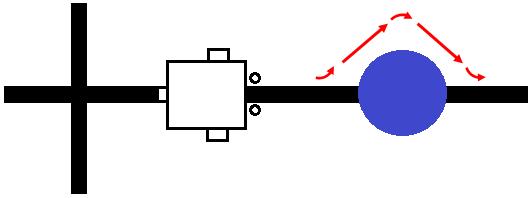
Finally, we need to add a new state “obstacle” to the state machine, for the robot to negociate or go around the obstacle and continue to follow the path line. This code is very simple to write, the robot only needs to turn to one side, go forward until surpassing the obstacle, turn again to the opposite side and go forward until reaching the path line (it is very advisable to use the light or color sensors to detect it so as to reach it with precision), and finally rectify the robot by making a small turn inverse to the previous one just before continuing to follow the path line.
Obstacle set up in the middle of the robot’s path and strategy to negociate it
State machine of the 4 step simple line follower with 2 light sensors with intersection
management, black rectangle detection and obstacle detection, “Initialization” state
(version 2, NXT)
State machine of the 4 step simple line follower with 2 color sensors with intersection
management, black rectangle detection and obstacle detection, “Initialization” state
(version 2, EV3)
As shown in the previous image, the diference between this second version and the first one is that we need to rename the “Initialization” state to “LS reading” (light or color sensors reading) and add a new state “Initialization” to the state machine to put the ultrasonic sensor reading. In this new “Initialization” state we just need to add the state machine variable with the “obstacle” value, when the ultrasonic sensor detects an obstacle at less than 20 cm (like in the previous version), and with the value “LS reading”, when it does not detect any obstacle, to make the robot follow the line. Finally, like in the previous version, we also need to add the same new case “obstacle” to the state machine, for the robot to negociate or go around the obstacle and continue following the path line.
What is the advantage of these two programing methods to negociate or go around an obstacle? The principal advantage is that the obstacle can be placed anywhere in the path, what would be more difficult to accomplish in a sequential programing. We need though to be careful with the programing code to avoid or go around the obstacle and come back to the path line, especially if there are several obstacles and if these are located in a curve, or in a staright line, or if there are walls in the path that prevent avoiding the obstacle from any side, etc.
We can imagine many more challenges to make more complex the previous programing code and a good exercise is to ask the students to invent their own challenge and add it to the previous exercise, by making the required changes to the state machine…
Acquired knowledge: With this pedagogical unit the students will understand with quite detail the data flow diagrams, the usefulness of the state machine programing and its big advantage over the sequential programing, by means of relatively simple examples, but which include decision making using sensors, counters to accumulate information and variables to pass information between blocks and program parts. This pedagogical unit can be especially useful to initiate young students’ teams that would like to participate in educational robotics competitions, like the rescue challenge of the RoboCup junior.
![]()
![]()
![]()
![]()